Inter-AS L3-VPN OPTIONS

There are three way to provision Inter-AS connectivity:
1. Option A: Inter-AS Back-to-Back VRFs (PE to CE concept).
2. Option B: Inter-AS VPNv4 Exchange (using eBGP).
3. Option C: Inter-AS VPNv4 Exchange between Route Reflectors.
All three options support VPNv4 and VPNv6 prefixes

1. Option A (Back-to-Back VRFs)
– One logical/physical interface per VRF in the interconnection
– One PE-CE eBGP/IGP session per VRF between ASBRs
– Each ASBR thinks the other ASBR is a CE
– IP traffic between ASBR, no labels

Inter-AS Option A

Advantages:
– Most secure, least invasive, support granular QoS
– No need for common RDs/RTs between ASNs
Disadvantages:
– A VRF for each customer, not scalable
– An eBGP session per VRF, not scalable
– No label switched between ASBR

2. Option B (MP-eBGP between ASBR for VPNv4)
– One physical/logical interface for all VRFs in the interconnection
– PE-ASBRs exchange routes directly using eBGP
– PE-ASBR exchange VPNv4 prefixes + labels using MP-eBGP with the advertising ASBR as the Next-Hop
– ASBR-ASBR link must be directly connected, could use GRE tunnel-considered directly connected
– VPNv4 prefixes and IGP PE prefixes are exchanged between ASBR
– Filter to redistribute only the peer’s address
– Filter Vrfs with “no bgp route-target filter all” command on the PE’s

Inter-AS Option B

Advantages:
– Less invasive than Option C
– More scalable than option A for high number of VRFs
– No VRF needed, less configuration when the number of customers grow
– Single MP-eBGP sessions between ASBR instead of multiple eBGP (per VRF)
– More secure then option C because internal IP for the SP are not exchanged, the SP only exchange labels VPN prefixes.
Disadvantages:
– More invasive than Option A
– Less scalable then option C because the PE-ASBR store all VPNs routes that need to be exchange
– Common RDs/RTs between ASNs (unless RT rewrite is used)

3. Option C (Multihop MP-eBGP between RRs, VPNv4+Labels)
– One physical/logical interface for all VRFs in the interconnection
– eBGP session between ASBRs with directly connected interfaces
– Two Options for Label Distribution for BGP NH addresses:
IGP + LDP or eBGP IPv4 + Labels
– ASBR exchange PE loopback address and labels
– Route Reflectors exchange customers VPNv4 prefixes over multihop MP-eBGP
– Packets have three labels
– Next-hop-unchanged on each VPNv4 RR for the eBGP session

Inter-AS Option C

Advantages:
– Separate VPNv4 and PE prefixes exchange, most scalable option
– The ASBR does not need to know the customers VPN prefixes. The ASBR is only used to exchange the SP internal IP.
Disadvantages:
– Internal IP (Loopback IP for PE) addresses a SP network is advertised and visible in another SP network, which is a security risk. Most SP wants to prevent any external visibility and access into their internal LSR IP.
– Because of the above property, option C is mostly deployed within a single SP or enterprise with multiple MPLS networks (i.e. merger).
– Common RDs/RTs between ASNs (unless RT rewrite is used)

Inter-AS Options

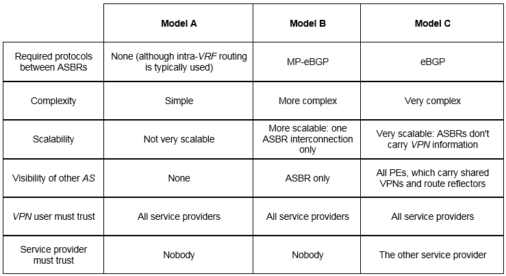
  • Some decision guidelines, from a security perspective:
    • If the number of shared VPNs and prefixes is small, consider model A. And it is the most secure option
    • If you are peering with another operator, that is, the other AS is not under your direct control and you cannot fully trust it, use model B. Model C is not recommended here.
    • If you are a single operator controlling all involved ASs, feel free to use model C. In this case, all your ASs behave a bit like a single AS, where ingress and egress PEs are in direct contact.

BRKMPL-2105 I-AS MPLS Solutions

Posted in MPLS, MPLS-VPN | Tagged , , | Leave a comment

Carrier Supporting Carrier (CsC) Design

  • Defined in RFC 4364
  • Also known as Hierarchical MPLS VPN service since MPLS VPN customer carrier subscribes MPLS VPN service from a MPLS Backbone provider.
  • VPNs inside customer carrier/s network are transparent to the backbone MPLS VPN Service Provider

 CsC design


Two ways for exchanging routes and labels:

  • Using IGP for route exchange plus LDP for label exchange – Like normal MPLS VPN PE-CE routing (static/RIP/EIGRP/OSPF), but with MPLS enabled under the VRF interface on the CSC-PE side and the CSC-CE side.
  • Using BGP for both route and label exchange – Using eBGP between the CSC-PE and CSC-CE routers, like normal MPLS VPN PE-CE.

Security:

  • Authentication on LDP/BGP sessions
  • Apply max prefix limits per VRF
  • Use of static label between CSC-CE and CSC-PE
  • Route Filtering (with route-map/match and set capability) because Customer Carrier may not want to send all the internal routes to MPLS VPN backbone provider

Some Recommendations:

  • Do not use static default routes on CSC-CE (end to end LSP is required across the VPN and MPLS VPN backbone
  • Use dynamic protocol on CSC-CE to CSC-PE (see note below)
  • Set Next-Hop-Self on Pes carrying external routes
  • If using RRs in customer carrier network, set next-hop-unchanged on RRs.

Note:

When using eBGP + label between the CSC_PE and the CSC_CE we need to use the “as-override” on the CSC_PE if the CSC_CE routers are using the same ASN (as if this is an ordinary PE-CE routing protocol).

Using BGP for CSC is the recommended solution, due to the following facts:

  • BGP takes the place of an IGP and LDP in a VPN VRF table since we can use BGP to distribute routes with their MPLS labels, and for sure using a single protocol instead of two simplifies the configuration and troubleshooting.
  • BGP is the preferred routing protocol for connecting two ISPs, mainly because of its wide scale routing policies and ability to scale.

Source
BRKMLP-2105 I-AS MPLS Solutions
Carrier-supporting-carrier-the-whole-story-1

Posted in BGP, Design, MPLS-VPN | Tagged , , | Leave a comment

Layer2 and Layer3 Campus Network Design

Layer 2 Access with Layer 3 Distribution

  • Each access switch has unique Vlan
  • No Layer 2 loops
  • Layer 3 on link between Distribution switches
  • No Spanning-Tree blocked Links
  • Fast convergence, only dependent on FHRP

L2 access L3 distri

Some Best Practices:

  • Use rapid-pvst (802.1w) or MST (802.1s) instead pvst+ (802.1d)
  • tune FHRP and STP root bridge to load balance uplinks
  • Tune CEF load-balancing
  • summarize to the core

Layer 2 Access with Layer 2 and Layer 3 Distribution

  • Some Vlans span multiple access switches
  • Layer 2 loops
  • Layer 2 and Layer 3 on link between Distribution switches
  • Spanning-Tree Blocked links

L2 access L2 distri

One solution : Use MEC (Multi-Chassis EtherChannel) => VSS(6500) or VPC(Nexus)

VSS - VPC

Routed Access Design Best Practices:

  • Use routed point-to-point link (quick convergence versus L2)
  • ECMP to avoid convergence ( quick reroute)
  • Tune CEF L3/L4 load balancing hash (for best load balancing on equal costs multipath)
  • Build triangle not square for quickly convergence (No need to recalculate new path)
  • Insure redundant L3 path to avoid black holes
  • Summarize distribution to Core to limit black hole (Requires a link between the distribution switches)

Rouer access design

Constrains:

  • Can’t span Vlans across multiple wiring closet switches
  • IP addressing
Posted in Design | Tagged , , | Leave a comment

BGP as PE-CE Routing Protocol

– BGP is the most widely used PE-CE protocol in the MPLS-VPN environment
– Enterprise Customers choosing BGP as PE-CE protocol to peer with the Service Provider in MPLS-VPN networks should think about:
•      Same AS number at all the customer locations
•      Different AS number at the Customer Locations
•      With Back Doors
•      Private AS number vs. Public AS #
•      Multi-homing and Load-balancing options
•      Customer sites connected to two or more Providers


• MP-BGP Extensions
BGP has been extended in the form of Multi-protocol (MP-BGP) to carry routes from multiple address families
– MPLS uses the VPNv4 AF
– VPNv4 AF is a 12-byte field:
.        Route Distinguisher [RD]: 8 bytes
.        IPv4 Address: 4 bytes
– Route-Target Attribute
– Label value


• Same AS at Customer Sites
• Customer Site A want to sends the BGP routes to its PE1
• PE1 advertises to all, the iBGP-VPNv4 peers
• Remote PEs advertises those routes to the CE BGP peer at their sites
• Remote Sites CE routers will not accept the routes as they see their own AS in the AS-Path
• MPLS-VPN PE routers need to be configured with the “AS-OVERRIDE” option so that remote CE Routers will not see their own AS in AS PATH.


• Different AS at Customer Sites
No particular problem.


• With Back Door Connections
– When the MP-BGP route are sent to CE2 or CE3 for CE1, the route will be learned as an eBGP route with Admin distance of 20
– If the same route comes via the back door (e.g. OSPF, IS-IS or EIGRP), Admin distance will come into consideration
– Since eBGP has Admin. Distance of 20—MPLS-Core will be used to reach the destination

BGP Backdoor
• Private AS vs. Public AS
– Enterprises that get connected to the Service Provider MPLS-VPN Network can use a BGP Private AS number (64512-65535)
– The Private AS number will be hidden from the global Internet
– The Customer BGP AS will only be used to connect the different customer entities

Source BRKRST-2332 L3 VPN: PE-CE Operation and Deployment

Posted in BGP, Routing Protocol | Tagged , , , | Leave a comment

EIGRP as PE-CE Routing Protocol

• PE-CE: Operation
– CE runs EIGRP as before where as PE runs EIGRP-VRF process per VRF/AS
– EIGRP routes are distributed to sites customer via MP-iBGP on the MPLS-VPN backbone
– There are no EIGRP adjacencies or EIGRP updates in MPLS/VPN backbone
– EIGRP information is carried across MPLS/VPN backbone by MP-BGP in new extended communities (set and used by PE’s)

PE-CE EIGRP Extended Community
EIGRP ext.Community


• Customer Sites in the Same EIGRP AS
– AS CE-Sites are in the same-AS, routes will be learned with normal EIGRP attributes
– MP-BGP will carry the EIGRP attributes natively as part of the BGP update (EIGRP AS #, EIGRP Metrics)
– Customer sites will see remote sites as part of their normal EIGRP domain
– Remote Site routes are being on the Local PE routers with Internal EIGRP Admin Distance of 90 and with Hop Count of 2

EIGRP Same AS


• Customer Sites in the Different EIGRP AS
– Customer sites are in different EIGRP AS
– CE Sites will learn the remote-CE-site routes as EXTERNAL routes
– This is normal behavior due to the different EIGRP AS
– MP-BGP on the PE routers will carry the EIGRP routes with their normal attributes
– Remote Site routes are being on the Local PE routers with External EIGRP Admin Distance of 170 and with Hop Count of 1

EIGRP Different AS


• Customer Sites with Backdoor Links
– Customer wants to use the MPLS-VPN core for the Sites connectivity
– Use the Back-door links in case of a failure (they usually are low-speed links)
– Use EIGRP attributes on backdoor links for the Sites Connectivity (example: delay)
– Network should work as expected if connectivity is lost through MPLS-VPN Core

EIGRP Backdoor


Source BRKRST-2336 EIGRP Deployment in Modern Networks

Posted in EIGRP, Routing Protocol | Tagged , , , | Leave a comment

OSPF as PE-CE Routing Protocol

• What feature we can use to prevent routing loop for dual home CE?
PE set “down bit” for LSA type 3 and reject LSA type 3 from CE with “down bit” set
See OSPF Divers.

• What feature we can use to keep external route as LSA type 5 or type 7 for network with dual OSPF processes when using MPLS L3VPN as inter-site connection?
Configure domain-ID on PE. PE with same domain-ID advertises LSA 1/2/3 as LSA3 to CE. PE with difference domain-ID advertises all LSA as LSA type 5

OSPF Router ID


• Summarization: Ingress PE
– What if you want Site1 (area 1) to send a summary route to all other
– Summarization is not possible since ABR does not exist in Site1.
– PE-1 can summarize via BGP and advertise a aggregate block to all other sites

OSPF Summary Ingress


• Summarization: Egress PE
– What if you need to send a summary route to Site3 (area3)?
– Can’t summarize from each individual site; no ABR exists within the sites (area1 or area2)
– Summarize all the other site routes, on PE-3
– Type-5 metric will be selected from best to BGP MED (multi-exit discriminator)

OSPF Summary Egress
But be-careful with Loop:
– Summary is originated in OSPF
– Summary route will be propagated to all sites as a result of redistribution from OSPF into BGP
– Summary route should be filtered while redistributing OSPF into BGP on PE3 unless it is desirable to send summary to some select PEs


• What feature we can use to prefer MPLS Backbone link over intra area backdoor link?
Run “OSPF Sham-link” between PEs and adjust cost on backdoor Link.

OSPF Sham-link

Source ccdewiki
Source BRKRST-2337 OSPF Deployment in Modern Networks

Posted in OSPF, Routing Protocol | Tagged , , , | Leave a comment

OSPF Divers

Types of Link State Advertisements (LSAs)
Type1 = Router Link
Type2 = Network Link
Type3 = Network Summary
Type4 = ASBR Summary
Type5 = External
Type6 = MOSPF
Type7 = NSSA External

OSPF Area’s
Diff OSPF areas type

“Totally” NSSA scales better due to the reduction in LSAs and routing prefixes.
The drawback is that you will have less optimal routing with regards to inter-area prefixes (both internal and external).
If that is acceptable, pick Totally NSSA.
If optimal inter-area routing is required, choose NSSA.

OSPF Path Selection Order
Internal-Area = O
Inter-Area = OIA
External Type1 = E1
External Type2 = E2
NSSA Type1 = N1
NSSA Type2 = N2

Tools for Fast Convergence
Failure Detection Time (Fast Hello or BFD)
Even Propagation Time
(It is required that LSAs are always flooded prior to SPF run)

SPF Run Time (SPF run-time delay)
RIB FIB Update Time

The use of Incremental SPF allows to further minimize the amount of calculations needed when partial changes occur in the network.

OSPF “DOWN” bit set (to prevent loops in multi-homed sites)
= Automatically set in all summary LSA 3 (not in LSA 5) when routes are redistributed from MP-BGP into OSPF.
• Provide loop prevention for type 3 Lsa
• Down Bit is set on route advertisement from PE=>CE
• PE will not accept routes with Down Bit set from CE

When a prefix with DOWN bit set is received on an interface which is configured with VRF, that LSA is dropped. (correct sentence is: that LSA is not considered during the SPF calculations).

The solutions to this problem:
A) Is to configure the command “capability vrf-lite” on the customer router(s), but this is not supported on all IOS:
B) Configure different domain-IDs as this will force all redistributed routes to become external (LSA 5, thus bypassing the DN bit check)

OSPF DN

OSPF: P-bit Setting in Type-7 LSAs

P-bit = (P – propagate) only used in type-7 LSAs to tell the ABRs to translate that type-7 LSA into a type-5 LSA.
This P-bit is also used as a routing loop prevention mechanism.

OSPF P Bit

Source RASESH PATEL

Posted in OSPF, Routing Protocol | Tagged , , | Leave a comment

mVPN / Multicast over MPLS / Rosen Draft

Basic Concept of MVPN

• The Service Provider has an IP Network with its own unique IP multicast domain (ie: P-Network).
• The MVPN customer has an IP Network with its own unique IP multicast domain (ie: C-Network).
• The Service Provider MVPN network forwards the customer IP multicast data to remote customer sites. To achieve this, customer traffic (C-packets) is encapsulated at the Service Provider PE inside P- packets. The encapsulated P-packet is then forwarded to remote PE sites as native multicast inside the P-Network
• During this process, the P-Network has no knowledge of the C-Network traffic. The PE is the device that participates in both networks. Note there may be more than one Customer Network per PE.

NOTE
The use of GRE in a multicast domain is not the same as the overlay solution in which point-to-point GRE tunnels are used between CE routers. The GRE tunnels used here are between PE routers in a multicast configuration. The tunnels can be considered point-to-multipoint connections if PIM SM is deployed or even multipoint-to-multipoint if using PIM Bi-Dir.
Therefore, the use of GRE for multicast domains is inherently more efficient than GRE overlay.
PIM SM or SSM are the only multicast modes supported in the P-network for mVPN.


MDT

• Default Tree
– is used for customer Control Plane and low rate Data Plane traffic
– created by default, all PEs that run multicast VRF are part of the tree
– can use SM and SSM, SSM is preferred because without RP, it is simplier to deploy and maintain
• Data MDT
– created dynamically when there is active multicast source and listeners
– only PEs with active source or listen will join the tree
– Customer traffic initially run on the default tree, when the traffic crossed over the configured threshold, a data MDT is built.

Source ccdewiki
Multicast VPN Design Guide


Operation of Multicast MPLS VPN

  1. Default MDT is enabled per customer VRF on every PE router that will forward
    multicast packets between customer sites. The VRF on the PE routers thus enabled
    for multicast forwarding is also called the multicast VRF (mVRF).
  2.  Default MDT enables multicast forwarding for all PEs where the VRF resides.
  3. Control and data packets are transported per VRF over default MDT. Therefore, all
    low bandwidth data that is transported over the default MDT will be delivered to PEs
    where the VRFs reside. Hence, the default MDT is always present.
  4. A Data MDT for higher bandwidth sources can be created on the PE routers per VRF, and only routers that are part of the multicast tree for the high bandwidth source receive the multicast packets generated by the high bandwidth source.The data MDT is created on demand for mVPN (S, G) higher bandwidth traffic.
    MDT group addresses are defined by the provider and are unrelated to the groups used by the customer.
    Access to the MDT is via a multicast tunnel interface on PE routers where the PE router always functions as the root of the MDT if it is connected to the CE router containing the multicast source.


Configuration sample for Multicast MPLS VPN

• MPLS VPN-CE Router Configuration
– Enable Multicast Routing Globally
– Enable PIM on All Interfaces

• MPLS VPN-CE Multi-VRF Router Configuration
– Enable Multicast Routing Globally
– Enable PIM on VRF All Interfaces

• MPLS VPN- PE Router Configuration
– Enable Multicast Routing Globally or Per VRF
– Configure the Default MDT and Data MDT for the VRF under VRF Definition
– Enable PIM on All VRF and Core Facing Interfaces
– Enable SSM Glogally

• MPLS VPN-P Router Configuration
– Enable Multicast Routing Globally
– Enable PIM on All Interfaces
– Enable SSM Glogally

Pim adjacencies in MPLS


Multicast IPv6 Tunnelling Supports

The following protocols supports IPv6 multicast:
– IPv6inIPv4
– Dual-Stack

The following protocols do not support IPv6 multicast:
– ISATAP
– 6to4
– 6PE
– 6VPE

Source ccdewiki


IPv6 Multicast Deployment Models

• There are two models:
– Any Source Multicast (ASM)
– Source Specific Multicast (SSM)

• What is ASM?
– It requires RP
– It uses SPT between Source and RP, and ST between listeners and RP on the initial connection setup but could switch to SPT if the SPT is a more efficient path.
– The PIM model to use is PIM-SM
• What is SSM?
– It does NOT use RP
– It uses SPT (S,G) between listeners and Sources
– The PIM model is PIM-SSM

• When to use ASM?
– When you have distributed Sources, like an enterprise network with multiple DCs and multicast sources in all these DCs
• When to use SSM?
– When you have few sources, like a SP network with a centralized content streaming servers
– When you have more than one PIM domains, because there is no mechanism to exchange RP information between domains for IPv6
– When you do not want to manage RP

Source ccdewiki

Posted in IPv6, MPLS, MULTICAST | Tagged , , , , | Leave a comment

MULTICAST Rendez-vous Point

A Rendezvous Point (RP) is a router in a multicast network domain that acts as a shared root for a multicast shared tree.

• Static RP
• Bootstrap Router (BSR)
• Auto-RP
• Anycast-RP
• Phantom RP
• Embedded RP


  • Static RP
    – Not scalable in large network (manual configuration required on every router in the multicast domain)
    – Not provide redundancy or load-balancing.
    – Can be combine with Anycast RP to provide RP load sharing and redundancy


  • Bootstrap Router (BSR)
    – BSR provides dynamic distribution of RP-to-group mapping information across a PIM domain.
    – The BSR broadcasts the “RP set” to all routers in the domain.
    – It ensures that all routers in the PIM domain have the same RP cache as the BSR.
    – It is possible to configure the BSR to help select an RP set from BSR candidate RPs.
    – Auto-RP and BSR protocols must not be configured together in the same network
    – BSR messages are flooded hop-by-hop throughout the entire network.
    – Use ip pim bsr-border command on the edge router connecting to MSDP domains.


  • Auto-RP
    – Cisco Proprietary
    – Auto-RP is not supported for IPv6 Multicast
    – Auto-RP is a mechanism to automate distribution of RP information in a multicast network.
    – BSR and Auto-RP protocols must not be configured together in the same network.
    – Operates using two basic components, the candidate RPs and the RP mapping agents.
    – Candidate RPs: advertise their willingness to be an RP via “RP-announcement” messages (group 224.0.1.39: CISCO-RP-ANNOUNCE).
    – RP mapping agents join group 224.0.1.39 and map the RPs to the associated groups. (224.0.1.40: CISCO-RP-DISCOVERY)

Auto-RP

– No configuration needed on every router separately (except on candidate RPs and mapping agents).
– Auto-RP supports the use of multiple RP’s within a network to serve different group ranges and allows configurations of redundant RPs.
– Because multicast is used to distribute this information it requires Dense mode for scalability or use ip pim autorp listener along with access-list command to put the spare mode interface in dense mode for two Auto-RP groups (224.0.1.39 & 224.0.1.40)


  • Anycast-RP
    – Anycast RP is used to define redundant and load-balanced RPs
    – Anycast-RP provides RP failover and redundancy.
    – MSDP used for Anycast RP is an intradomain feature that provides redundancy and load-sharing.
    – Two or more RPs are configured with the same IP address on loopback interfaces.
    – The Anycast RP loopback address should be configured with a 32-bit mask.

Anycast-RP

– You can use BSR or Auto-RP to automate RP distribution.


  • Phantom RP
    – Phantom RP provides fast failover of IP multicast but no load-balancing.
    – Two or more RPs are configured with the same IP address on loopback interfaces, but with different mask length.
    – You can use BSR or Auto-RP to automate RP distribution.
    – This is only option to configure Bidir PIM redundancy.


  • Embedded RP
    – Embedded RP defines an address allocation policy in which the address of the RP is encoded in an IP multicast group address.
    – This allows an easy deployment of scalable inter-domain multicast and simplifies the intra-domain multicast configuration as well
    – There is no need to pre-configure routers with the RP address information. Routers can automatically extract and use the RP information from the IPv6 multicast group address. This allows for a large number of RPs to be deployed anywhere in the Internet.
    – Embedded RP requires no change in protocol operations. It can be considered an automatic replacement for static RP configuration.
    – Support’s only IPv6 and Source-Specific multicast.

Embedded-RP


  • Comparison of RP Mechanisms

tableau-RP

 Cisco: Rendezvous Point Engineering

Posted in MULTICAST | Tagged , , , | Leave a comment

Redundant Phantom Rendez-vous Point / Longest Match

Because multicast source information is no longer available in Bidir, the Anycast/MSDP mechanism used to provide redundancy in sparse-mode is not an option for Bidir.
That mechanism relied on the announcement of active sources through MSDP, which is not available in Bidir.
In Bidir, redundancy consists of a primary/ secondary model, there is no load sharing as was possible with the Anycast-rendezvous point sparse-mode case (it’s impossible to load share without maintaining source information).

Bidir

The preferred method for providing Bidir rendezvous point redundancy can be designed using loopback networks with different mask length.
This mechanism relies on unicast routing longest match route lookups to guarantee a consistent path to the rendezvous point.
In this case the rendezvous point address is still a “phantom” address (that is, it is not associated with any physical entity).
It is only necessary to ensure that a route to the rendezvous point exists, to maintain rendezvous point reachability. For this we will employ loopback interfaces in the primary and secondary routers with different netmask lengths.
The way the primary/secondary relationship works in this situation is by advertising routes for the rendezvous point with different netmasks.

Posted in MULTICAST | Tagged , , , | 1 Comment